In this part you’ll place the majority of the components onto the bread board in preparation for imaging. If you have your axes properly laid out, you shouldn’t run into any problems. This part is broken up into the following sections:
a) 660 nm beam path
- From the previous step, your 660 nm LED should be set at 170 mm above the table. Double check just to be sure, and adjust if necessary.
- Adjust the height of one of the aspherical condensing lens assemblies such that the center of the lens is 170 mm
- Starting from the right hand side (where the DMD is) count 11 holes left. Line up that column of holes with the illumination axis drawn on the breadboard. This will be the location of the 660 nm LED emitter. Rotate the assembly until the emitter is poised over that intersection and the LED is pointing at the DMD.
- Screw the base plate of the 660 nm LED assembly to the 12th column of holes. This will make the base plate of the assembly roughly vertical. The space to the left will be used for a screen so you don’t want it blocked by the base plate.
- Turn on the LED to make sure the LED is pointed at the DMD
- Take the aspherical condensing lens you set the height of in step ii and place it in front of the LED with the flat side facing the LED.
- As a starting point, place the condensing lens 1 focal length (20 mm) from the emitter. This will roughly collimate the beam.
- Slide the condensing lens towards and away from the emitter to get the brightest possible spot that fills the DMD surface. There is a tradeoff here: moving the lens farther from the emitter will collect less light, but will focus it into a smaller area. Moving it closer will collect more light, but the spot size on the DMD will be larger. The optimal location will be close to the focal length of the lens, but probably not exactly.
- Once the position is established, rotate the assemebly so you can screw the base plate into the 10th column of holes (counting from the right).
- If necessary, rotate the post holding the lens to ensure the flat side is parallel to the face of the LED. If you rotate the post you may need to shift the position of the lens slightly to make sure the center of the beam hits the DMD.
- If the beam is hitting too low, or too high, verify that the height of the LED and condensing lens are correct. Move the condensing lens up or down to make sure the beam is centered on the DMD.


Optional bonus step: At this point, you can project an image using the DMD. Grab the achromatic lens assembly and set the height to roughly 170 mm. Place it about 75 mm (3 inches) in front of the DMD along the projection axis. Use the DMD software to set the test image to “Checkerboard.” You should see a checkerboard appear on the DMD. Take a white piece of paper and follow the beam after it passes through the lens. At a certain point the image of the checkerboard should be focused on the paper.
b) Set up the camera to view the DMD
Because the two NIR wavelengths are hard to see, we’ll use the camera to help with the alignment. Before continuing, make sure LabView, the NI Measurement and Automation Explorer (MAX), and the Vision Acquisition System (VAS) module are installed on your PC.
-
- Attach a base plate to a 4 inch post holder.
- Insert an 8 inch post (TR8) into the holder.
- Starting from the front left corner count five holes to the right and 8 holes back. This is the position you want your post holder to be. Place the center of the post holder at that spot and use a cap screw to attach the base plate to the table
- Put a right angle adapter onto the 8 inch post and slide a 6 inch post through the second aperture such that the large side (with the 1/4-20 hole) is facing you.
- Use a 1/4-20 set screw to attach the post to the camera tripod holder.
- Loosen the right angle adapter to set the camera 170 mm above the breadboard surface and aim it at the DMD.
- Attach the C-mount lens to the camera
- Plug in the USB3 cable to the camera and to your PC.
- Open Measurement and automation explorer (MAX)
- You should see an entry for your camera. Click it and press “Grab.” You should see a live feed of the images captured by the camera. Adjust the focus and aperture of the lens to get the DMD in focus and avoid saturation.

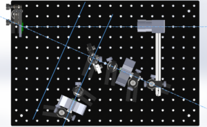
Model of the current state of the assembly with the camera imaging the DMD face. This will help align the invisible NIR wavelengths 
Camera pointing at DMD after placement of NIR wavelengths
c) 730 nm beam path
The next two steps will be quite similar to the step a and will be presented in slightly less detail.
- Adjust the height of the 730 nm lens assembly so the LED emitter is 170 mm above the table
- Adjust the height of one of the condensing lenses so the center of the lens is the same height
- Adjust the height of the first dichroic mirror so the center of the mirror is 170 mm in height. Double check to make sure it is the correct dichroic.
- Start by placing the dichroic at the intersection of the lines you’ve drawn for the 730 nm axis and the main illumination axis. Make sure to center the mirror over this intersection and not the post, or post holder.
- Place the LED along the 730 nm illumination path pointing toward the dichroic. The post should be close the second line of holes from the back. This will leave enough room for the condensing lens.
- Set the angle of the dichroic mirror by making sure the LED is pointed directly at along the 730 nm axis and rotate the mirror while looking at the live image from the camera. When you see the reflected light centered on the DMD tighten the lock nut on the post holder. Double check the height as well as the position of the mirror over the intersection of the 730 nm and illumination axes. If the position is off move it into the correct position and repeat this step. Keep repeating this step until the position and angle are correct.
- Place the lens along the 730 nm axis about 20 mm away from the LED with the curved side facing the LED
- Move the lens left, right, forward, and backward to maximize the intensity on the DMD (see step 3a). Before finalizing the position, make sure the flat side of the lens is perpendicular to the 730 nm axis. If it’s not, fix it, and adjust the position again.
d) 850 nm beam path
Repeat the part 3c but using the 850 nm axis and LED. Everything else should be the same. When you’re done, verify that the beam from the 660 nm LED is passing through both dichroic mirrors.
